NEWS CENTER
How to Install an 80 GHz Radar Level Meter in a Tall Silo: Beam Angle and False Echoes
Huachuang measurement and control Huachuang measurement and Control Technology Co., Ltd 2026-09-08 14:36
In cement, mining, coal, grain, feed and building-material applications, silos are often tall and large, with internal inlet pipes, reinforcing members, ladders, supports or dust-collection structures. The material surface is not always level, and different filling and discharge conditions can create changing angles of repose. If the radar signal is directed toward the silo wall or an internal structure, the received echo may contain reflections from fixed obstacles. This can lead to a false level, unstable readings or a displayed level that does not represent the actual inventory.
Beam angle is an important factor when assessing radar installation. A narrower beam concentrates more of the radar energy in the intended measurement area and can reduce the probability of interference from the wall and nearby structures. However, a narrow beam does not eliminate the need for correct installation. The mounting point must still be selected according to silo diameter, measuring distance, obstacle locations, material profile and filling or discharge conditions. For a tall silo, selection and installation should answer two questions at the same time: can the radar receive a reliable material echo, and does the measurement path avoid major interference?
According to HCCK’s official HCDAR-81 product information, the model is intended for liquid, granular and dusty material measurement. Its measuring range is 0–120 m, beam angle is 3°, response time can be as short as 0.6 seconds depending on parameter settings, medium temperature range is -40 to 120°C, process pressure range is -0.1 to 2 MPa, and accuracy is less than 2 mm. The same product information describes the HCDAR-8X series as using 76–81 GHz FMCW technology, with two-wire 4–20 mA, four-wire 4–20 mA and RS485 output options.
A 3° beam angle helps create a relatively concentrated measurement area in a large silo, but engineers should not evaluate the application from the “3°” value alone. As measuring distance increases, the area covered by the beam also increases. If the radar is aimed at the wall, a ladder or a support, even a narrow beam may receive an interference echo. Before installation, draw a simplified measurement path and confirm that there are no major obstacles directly below the antenna or within the beam. The radar should also be kept away from the strongest filling impact and falling-material path. For uneven powder or granular surfaces, assess whether the selected point represents the overall material level. If necessary, compare a point-level radar solution with a multi-point or 3D inventory measurement approach.
HCDAR-81’s official information also emphasizes aiming at the target level, keeping the signal as close to vertical incidence as possible and avoiding false echoes. This principle is particularly important in tall silos. The radar should measure along a stable and clear reflection path toward the material surface, rather than toward a wall, internal ladder or fixed structure. If the silo has severe eccentric material distribution, bridging or inventory-management requirements, a single-point radar reading represents the distance at the selected point and should not automatically be treated as the average level of the entire silo.
Before installation, confirm at least the silo height and diameter, normal and maximum level, material type and form, dust conditions, filling and discharge directions, ladder and support locations, process connection and required output signal. HCCK’s official HCDAR-81 page lists G3.5 thread and flange process connections. The project team should check the interface dimensions and available installation space against the actual silo. The antenna should be aimed as vertically as possible toward the material surface. The nozzle, flange and mounting bracket should not obstruct the antenna or place the radar close to a strong reflector.
Commissioning should not be based only on an empty and static silo. Observe the echo and displayed level under empty, low-level, normal-level, filling and discharge conditions. If an abnormal level remains at a fixed distance, inspect fixed internal structures and the mounting direction first. If the fluctuation occurs mainly during filling, analyze falling dust, the changing angle of repose and echo-strength variation. For silos with severe dust, strongly uneven surfaces or a need to understand overall inventory distribution, compare an 80 GHz radar such as HCDAR-81 with HCCK’s millimeter-wave 3D scanner. The former is intended for continuous distance measurement at a selected point, while the latter is intended to describe the spatial distribution, volume or inventory of material in a silo. The final solution should be selected according to the process objective, installation conditions and data requirements.
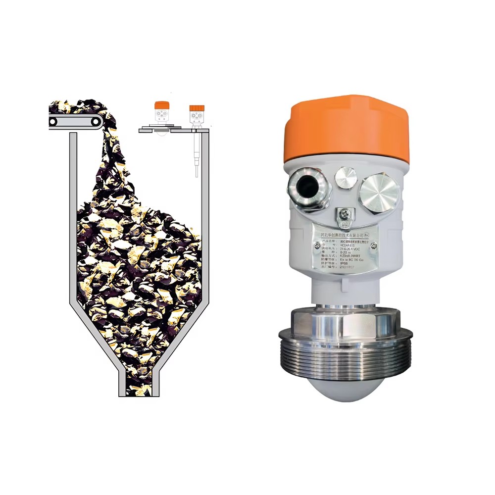
For a tall silo, beam angle is only the starting point for selecting an 80 GHz radar level meter. Measurement stability also depends on mounting direction, obstacle avoidance, material-surface characteristics and commissioning under real operating conditions. HCCK HCDAR-81 can be considered for liquid, granular and dusty material measurement projects. The final model, process connection and output configuration should be confirmed against the actual field conditions and HCCK’s latest official technical documentation.
For professional support, visit our Website at www.hhcck.cn/, contact our team via WhatsApp: +86 195 3225 4537, or Email: sales@hhcck.com.


South of Puhui Street, west of Guangsheng East Road, High tech Zone, Fengnan District, Tangshan City, Hebei Province





Technical support:

Tips
Submitted successfully
Back Index