NEWS CENTER
How to Measure Material Levels in Heavy Coating and High-Dust Applications: RF Admittance Anti-Buildup Principle and Selection Guide
Huachuang measurement and control Huachuang measurement and Control Technology Co., Ltd 2026-10-22 15:54
In industrial facilities such as electrostatic precipitator ash hoppers, cement raw meal silos, mining slurry tanks, asphalt mixing drums, flue gas desulfurization gypsum sumps, and chemical high-viscosity resin reactors, process media exhibit aggressive physical characteristics: high adhesion tackiness, dense suspended dust, abrasive slurry erosion, and violent material drop impact. Under these hostile operating conditions, traditional level measurement technologies encounter severe functional failures. First, mechanical contacting instruments (such as rotary paddle switches, vibrating tuning forks, and mechanical float switches) are rapidly coated and encrusted by damp powders or viscous residues. This heavy buildup impedes mechanical rotation or dampens fork vibration harmonics, triggering continuous false full-bin alarms and leading to mechanical fatigue, bearing seal failure, and motor burnout. Second, conventional capacitive level sensors suffer when conductive or semi-conductive buildup forms an equivalent parallel parasitic capacitance and leakage resistance between the probe and vessel wall. Standard capacitance bridge circuits cannot distinguish between true capacitance increases caused by rising material and residual capacitance from probe coating, resulting in severe baseline zero drift or output signal saturation. Furthermore, near coarse ore chutes or high-velocity drop zones, unarmored sensing rods are easily bent, fractured, or abrasive-worn, causing circuit shorting.
To overcome severe material adhesion, dust clouds, and mechanical impact, engineering teams must replace vulnerable mechanical switches and basic capacitive probes with robust measurement technologies capable of active anti-buildup immunity and zero mechanical wear. Instrumentation engineers must evaluate fluid dielectric properties (conductive vs. non-conductive), coating thickness, operating pressure, ambient temperature, particle granularity, and drop impact force to establish a dependable selection framework incorporating anti-coating bridge compensation, impact protection, and precision alarm telemetry.
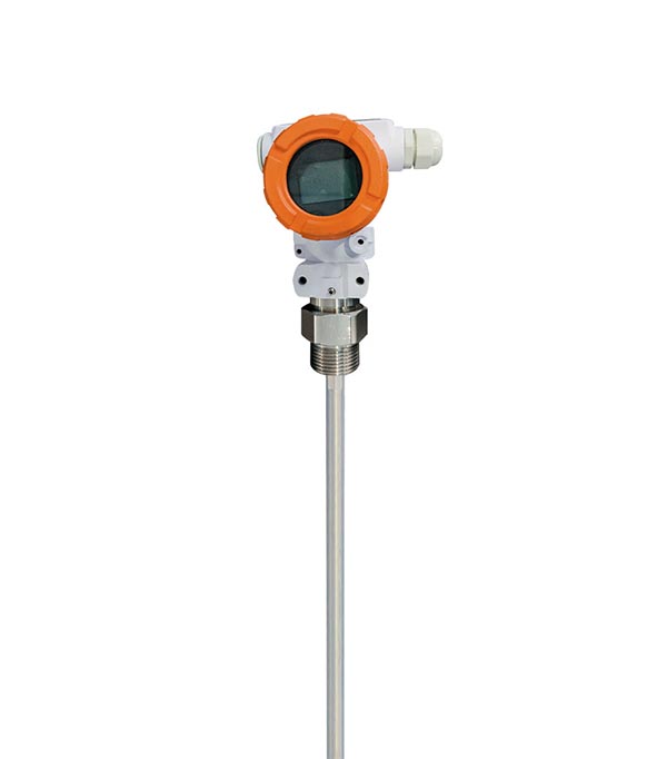
To eliminate measurement errors caused by material coating and parasitic capacitance, Radio Frequency (RF) Admittance level technology provides an optimal physical solution. The HCCK HCDN-503 RF admittance level transmitter utilizes high-frequency radio wave admittance circuitry combined with an innovative three-terminal driven-shield probe architecture, dividing the sensor into a primary sensing electrode, a driven shield electrode, and the grounded vessel wall. A high-frequency signal generator applies an RF AC voltage of identical frequency, amplitude, and phase to both the sensing and shield electrodes simultaneously. Because the potential difference between the sensing and shield sections remains zero, no current flows through the conductive material coating along the probe sheath to the tank wall. The high-frequency detection circuit measures only the reactive admittance change between the sensing electrode and the vessel wall as true material rises, completely isolating residual coating signals and eliminating false alarms.
In terms of technical performance and industrial durability, HCDN-503 delivers exceptional operational specifications: the instrument features a capacitance measuring range from 10 pF to 5000 pF with high accuracy exceeding <0.5% of actual measured value, process pressure capability from 0.1 to 2 MPa, operating ambient temperatures of −35°C to 65°C, and an IP67 robust enclosure rating. The sensing rod is encapsulated in heavy-duty impact-resistant, wear-resistant protective sheath materials with no moving parts, eliminating routine mechanical lubrication and cleaning maintenance. For field commissioning, HCDN-503 replaces complex calibration routines with an automated two-point bin height calibration (calibrating across any two known levels, such as empty and full bins), significantly reducing commissioning time. Powered by a standard 24 VDC loop, the transmitter provides a continuous 4–20 mA analog output alongside configurable limit alarm relay outputs, fulfilling continuous level monitoring and interlock requirements in small metal vessels, process hoppers, and storage tanks.
In plant mechanical installation, correct mounting geometry and electrical wiring are critical to maximize the anti-buildup performance of HCDN-503. First, mounting location selection must avoid direct alignment under the bulk material feed stream; if mounting constraints require positioning near an inlet chute, an inverted V-shaped angle iron deflector shield must be installed 200 mm to 300 mm above the probe to divert falling aggregates and absorb direct mechanical impact. Second, mounting nozzle design must ensure the nozzle diameter accommodates the probe and that the inactive driven shield insulation section extends completely past the inner vessel wall into the vessel interior, preventing dust accumulation inside the nozzle neck from bridging the shield circuit. For metallic vessels, the conductive wall serves directly as the reference ground; for non-metallic vessels (such as fiberglass or plastic tanks), an auxiliary parallel metal grounding rod or dual-element probe configuration must be installed.
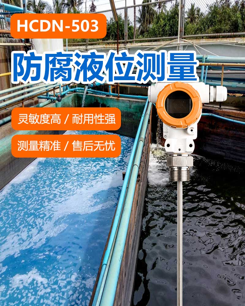
During field commissioning and routine operations, the automated two-point calibration feature of HCDN-503 simplifies startup: operators record baseline capacitance at low material level, raise the level to high mark to confirm the second point, and the internal microprocessor automatically computes and stores the linear operating slope. When requesting technical selection support from HCCK, plant operators should provide the process media type, dielectric properties (conductive or non-conductive), operating pressure, ambient temperature, vessel geometry (rod design accommodates spans up to 3 meters), mounting process thread size, and control interface requirements. The HCCK engineering team will configure the optimal probe length, protective sheath grade, and alarm settings to ensure stable, fail-safe level monitoring in severe coating and dusty industrial environments.
For professional support, visit our Website at www.hhcck.cn/, contact our team via WhatsApp: +86 150 2761 6330, or Email: sales@hhcck.com.


South of Puhui Street, west of Guangsheng East Road, High tech Zone, Fengnan District, Tangshan City, Hebei Province





Technical support:

Tips
Submitted successfully
Back Index