NEWS CENTER
Inaccurate Level Readings in Tall Solid Silos and Heavy Dust? 80GHz Narrow-Beam Radar Level Measurement Solution
Huachuang measurement and control Huachuang measurement and Control Technology Co., Ltd 2026-10-10 08:36
In industrial bulk storage applications such as cement clinker silos, fly ash tall bins, raw ore hoppers, coal bunkers, grain elevators, and large plastic pellet silos, continuous solid level monitoring remains a persistent operational challenge for automated plant control. Unlike smooth, reflective liquid surfaces, bulk solids naturally form asymmetric feeding cones, discharge draw-down funnels, sidewall material build-up, and sudden slope collapses during filling and emptying cycles. These irregular surfaces cause transmitted radar microwaves to scatter broadly or deflect away from the sensor's receiving axis instead of reflecting straight back. Furthermore, large industrial silos often range from 30 meters to over 100 meters in vertical height. As measuring distance increases, traditional lower-frequency radars (such as 26GHz or 6GHz) with wide beam angles (typically 8° to 20° or wider) project an expanding beam footprint that inevitably impinges on silo sidewalls, internal ladders, circumferential stiffener rings, and filling chutes. This generates strong false echoes that can easily overwhelm the weak true reflection from the distant material surface. Additionally, pneumatic conveying and gravity chute feeding generate extreme concentrations of airborne dust, which accumulates and crusts over the antenna face, severely attenuating high-frequency signal transmission and causing erratic signal loss, lock-up on fixed false obstacles, or sudden dropouts to blind-zone zero values.
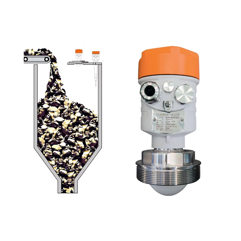
Faced with these severe process conditions, traditional mechanical plumb-bob level indicators carry persistent risks of cable breakage, weights buried inside collapsing piles, and inability to track dynamic level shifts in real time. Ultrasonic level sensors suffer severe acoustic velocity attenuation and signal absorption caused by suspended dust clouds and temperature stratification, making stable echo detection impossible in deep silos. Standard low-frequency radar transmitters struggle with low signal-to-noise ratios (SNR) and broad beam dispersal, failing to separate weak beat frequencies reflected from low-dielectric bulk solids (such as dry grain or plastic pellets) from surrounding structural clutter. To fundamentally resolve level distortion and signal dropouts in tall solid silos, the measurement solution must deliver superior microwave energy concentration (ultra-narrow beam angle), substantial measuring range margin, high-SNR signal processing capable of capturing weak diffuse reflections, and a dust-resistant lens antenna construction that ensures reliable penetration through heavy dust clouds and angled piles.
To completely eliminate structural false echoes and heavy dust attenuation in tall silos, HCCK delivers an advanced solid level measurement solution powered by the HCDAR-81 80GHz millimeter-wave Frequency Modulated Continuous Wave (FMCW) radar level transmitter. Operating at 76–81 GHz, the instrument provides an expansive measuring range of 0–120 m with an accuracy of <2 mm, incorporating an integrated PTFE lens antenna engineered to narrow the radar beam angle down to a focused 3°. The 3° concentrated beam angle focuses high-frequency microwave energy into a sharp, tight conical path. When measuring inside tall silos exceeding 50 to 100 meters in height, the beam travels straight along the silo vertical axis and penetrates dense dust clouds without striking sidewall seams, reinforcing ribs, internal inspection ladders, or filling pipes, physically eliminating sidewall obstacle interference from the signal path.
For advanced signal discrimination and dust resilience, HCDAR-81 utilizes wideband 80GHz FMCW modulation combined with high-speed Fast Fourier Transform (FFT) spectral analysis algorithms. This substantially enhances echo detection sensitivity and signal-to-noise ratio (SNR) on low-dielectric bulk solids and steeply angled surfaces, reliably tracking diffuse reflections even during high-rate loading and unloading cycles. The antenna face is constructed with smooth, high-density, corrosion-resistant PTFE lens material, featuring an extremely low surface adhesion coefficient that prevents airborne dust from caking and maintains long-term signal transmission efficiency. Operating reliably across process temperatures of −40 to 120°C and process pressures of −0.1 to 2 MPa, HCDAR-81 features robust IP68 ingress protection. It offers versatile signal interfaces including two-wire (4–20) mA HART, four-wire configurations, and RS485 MODBUS, enabling seamless integration with plant DCS, PLC networks, and automated inventory management platforms for continuous, maintenance-free silo monitoring.
To maximize the measuring stability of the HCDAR-81 solution in tall solid silos, plant engineers must observe proper mounting positioning and mechanical alignment. The mounting nozzle should be located at approximately 1/2 to 1/3 of the silo roof radius from the sidewall, ensuring it remains completely clear of direct filling streams from conveyor discharge chutes while maintaining at least 500 mm clearance from the silo wall to prevent structural interference and mechanical impact from incoming material. On arched or conical silo roofs, the antenna face must be aligned perpendicular to the vessel bottom; for bulk materials with steep angles of repose (such as coarse ores and clinker), an adjustable alignment swivel flange can be utilized to optimize the antenna orientation toward the dominant reflective slope. Furthermore, the mounting nozzle must feature a smooth, burr-free interior with minimal height, ensuring that the PTFE lens antenna face extends slightly below the bottom edge of the nozzle to prevent near-field internal ring echoes.
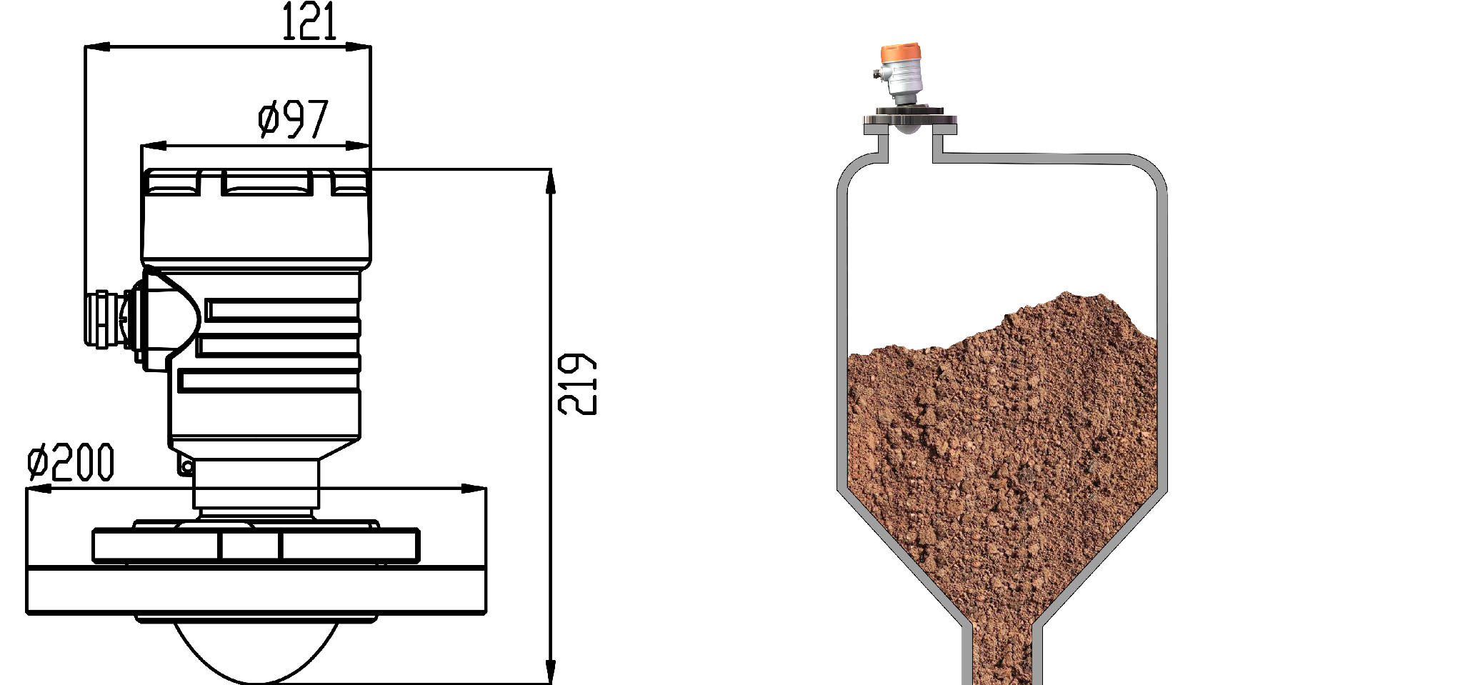
During technical consultation and solution selection, plant operators should provide the following field process parameters to the HCCK engineering team:
Silo physical geometry: Silo height, diameter, roof profile (flat, domed, conical), and available process connection specifications (flange size or thread rating);
Bulk material properties: Medium name (e.g., cement, fly ash, coal, iron ore powder, grain, plastic pellets), bulk density, particle size distribution, relative dielectric constant, and moisture content;
Process loading dynamics: Feeding method (pneumatic blowing, conveyor belt, gravity chute), maximum filling/discharge rates, maximum dust concentration, and expected angle of repose;
Process environment and electrical requirements: Maximum operating temperature and pressure, hazardous area explosion-proof ratings, power supply configuration (24 VDC or 220 VAC), and control network communication protocols (4–20 mA HART or RS485 MODBUS). HCCK engineers will utilize these operational parameters to configure the optimal process mounting flange, horn adaptation, and echo suppression parameters for long-term, maintenance-free silo operation.
For professional support, visit our Website at www.hhcck.cn/, contact our team via WhatsApp:+8615027616330, or Email: sales@hhcck.com.


South of Puhui Street, west of Guangsheng East Road, High tech Zone, Fengnan District, Tangshan City, Hebei Province





Technical support:

Tips
Submitted successfully
Back Index