This technical solution is developed for a project where radar level meters are installed on storage tanks in the customer's field tank area, with data collected via PLC modules, displayed through computer screen configuration, and alarm functions implemented. It comprises three systems: the radar level measurement system, the PLC module acquisition and transmission system, and the computer screen configuration display system. Based on the method of using the 80GHz HCDAR-81S radar level meter for liquid level measurement, advanced technical processing ensures precise measurement and output of oil tank liquid level data. Its advantages of fault-free operation and zero maintenance make it an ideal replacement for traditional weighing-based measurement tools.
Aiming at the technological requirements of installing radar level meters on your company’s storage tanks for liquid level measurement and data acquisition/transmission via PLC modules, the following solutions are proposed after investigation and demonstration by our technical team. Details are as follow:
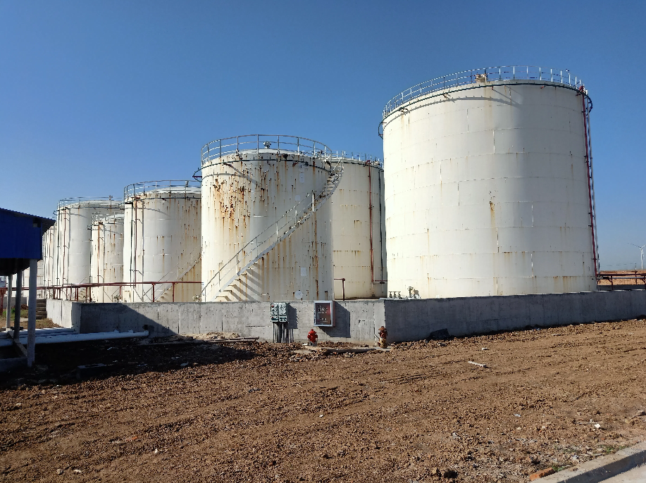
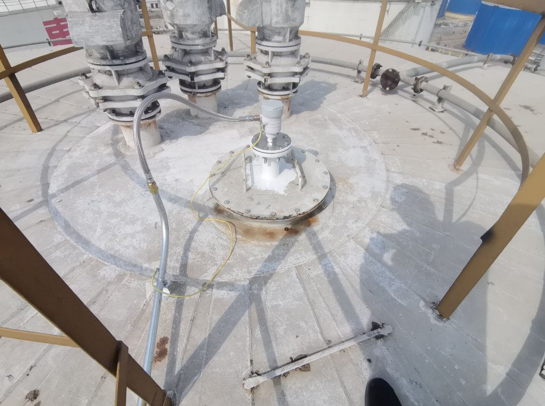
The oil tank liquid level detection system utilizes our independently developed HCDAR-8X series 80G high-frequency radar level meters, installed on the top of each storage tank. The radar level meters transmit detected liquid level signals to the analog acquisition modules of the PLC, which are then displayed on computer screens via network cables. The computer screens support alarm display and connect to external audible-visual alarms, triggering alerts when the liquid level reaches the preset upper alarm threshold. The monitoring room computer screens also enable radar range setting, alarm value configuration, and historical data curve storage.
Taking a complete set of storage tanks as an example, the system includes:
10 units of our 80GHz radar level meters
1 set of PLC control cabinet in the monitoring room
1 computer
Other auxiliary materials
This setup enables real-time liquid level measurement, audible-visual alarms, and historical level record query, ensuring both measurement accuracy and production safety.
Taking a single storage tank’s liquid level detection system as an example:
Functions:
During operation, the radar level meter continuously and stably measures the liquid level inside the tank, transmitting signals to the signal isolation distributors in the PLC control cabinet. These distributors process 4-20mA input/output signals and send the liquid level data to the analog acquisition modules of the PLC. The PLC connects to the monitoring computer via a network cable to display the liquid level on the screen. Alarm values can be set on the computer; when triggered, on-site audible-visual alarms activate, and the computer displays alarm indicators. Historical liquid level curves can also be viewed.
Stable and continuous measurement with real-time display of tank level parameters.
Non-contact measurement, minimal maintenance, no technical failures, and long service life.
Simple operation and safe automatic measurement.
On-site level display and audible-visual alarms for convenient field operation.
Transmission of 4–20mA standard signals to the main control room, with direct level display, upper alarm setting, and historical curve storage on the main control screen.
On-site radar level meters transmit liquid level signals to signal isolation distributors. A KVVRP 2×1.5mm² two-core shielded soft signal cable is laid between each radar and the PLC control cabinet. Communication between the PLC modules and the computer is achieved via a network cable.
Signal isolation: Eliminates interference to ensure accurate and stable signal transmission.
Protection: Safeguards PLC modules and provides lightning protection.
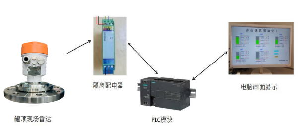
Figure 2: Overall Flowchart of Liquid Level Measurement, Data Acquisition/Transmission, and Screen Display
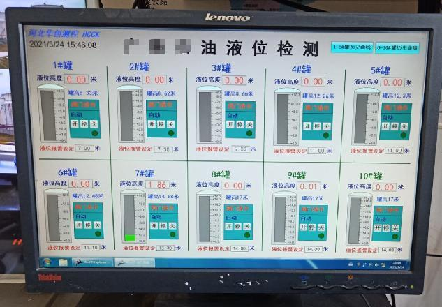
The display computer must support the Windows 7 operating system. Our professional technicians will install PLC programming software, data communication software, and screen configuration software, and perform PLC program development and screen configuration debugging. The computer must be equipped with a network card. Example display interface:
Tighten the cable glands at the radar’s inlet to prevent rainwater from entering the radar through the cable hole, which could cause power short circuits, damage, or malfunctions.
Lay an RVVP 2×1.5mm² two-core shielded cable between each on-site radar and the PLC control cabinet in the monitoring room.
Lay a shielded network cable between the computer and the PLC control cabinet (provided by Party B if the distance is short).
If you have any needs, please contact us!
Contact number: 400-851-0898


![]()


